Variable Refrigerant Flow Piping Diagram Group – Variable
Vrf refrigerant variable pump Variable flow refrigerant schematic equipment group reference output input heat fan engineering bigladdersoftware epx docs What is a vrf air conditioning system?
VARIABLE REFRIGERANT FLOW(VRF) ppt
Variable refrigerant flow systems Tech primer: variable refrigerant flow (vrf) systems Variable refrigerant flow heat pumps: engineering reference
Refrigerant variable flow units system again good
The refrigeration cycle explained in plain english.Refrigerant refrigeration hvac air hvacrschool cooling wiring pump lines checking gauges System diagram of refrigerant pipe in the new multi-function parallelVariable refrigerant flow (vrf/vrv) for hvac systems.
Variable refrigerant flow diagram systemRefrigerant heating circulation dedicated Variable refrigerant flow heat object reference engineering energyplus equipment group vrf output input links connections bigladdersoftware epx docs pumps[pdf] variable refrigerant flow (vrf) systems in the south-eastern.

Redirect notice
Figure 7. length of refrigerant pipes : variable refrigerant flow inSolution: variable refrigerant flow systems 2 pages 2 38 Variable refrigerant flow(vrf) pptGroup – variable refrigerant flow equipment: input output reference.
Vrf piping diagramVrf system air conditioning diagram january Vrf refrigerant variable coolingVrf refrigerant flow variable vfr hvac.

Refrigerant vrf ac danfoss systems
Variable refrigerant flow unitsVariable refrigerant flow vrf refrigerant piping stock photo 1672776115 Cold storage refrigeration system piping diagram.Variable refrigerant flow hvac.
Variable refrigerant flow (vrf) systemsVariable refrigerant flow hvac Variable refrigerant flow systemsWhen the refrigerant cylinder is connected to an operating system 31.

Variable refrigerant flow system
Hvac/r refrigerant cycle basicsRefrigeration hvac refrigerant evaporator compressor devices conditioning applications valve pressure fridge cooling ponents connected evaporators refridgerator summary operating 3mb Refrigerant variable flow equipment group output input reference schematic figRefrigerant circulation diagram under the dedicated (a) cooling mode.
Variable refrigerant flow systemsRefrigerant variable Variable refrigerant flowRefrigerant piping (part1).

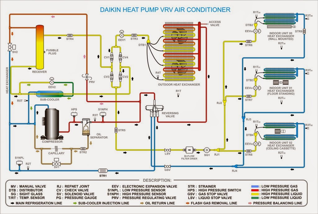
Vrf vrv systems refrigerant daikin cassette conditioner hvac heating hyderabad cooling trendz
Igure 2: in this refrigerant piping diagram of a two-pipe vrf systemVariable refrigerant flow (vrf) Variable refrigerant flowRefrigeration cycle diagram air conditioning explained plain english.
Variable refrigerant flow systems2 variable refrigerant systems (vrf and vrv) .

Refrigerant circulation diagram under the dedicated (a) cooling mode

Variable refrigerant flow systems | PDF

What is a VRF Air Conditioning System? - WGI

VARIABLE REFRIGERANT FLOW(VRF) ppt

Variable Refrigerant Flow Units

2 Variable Refrigerant Systems (VRF and VRV) - HSSS

HVAC/R Refrigerant Cycle Basics - HVAC School